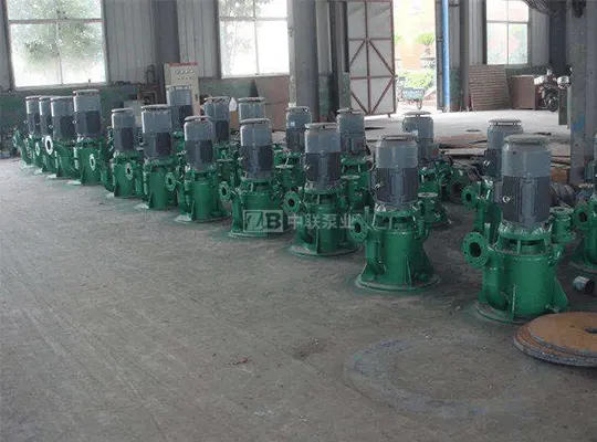
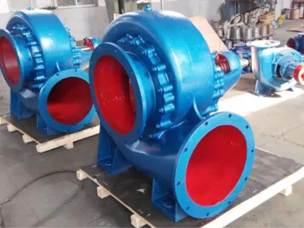
The WFB self-priming sewage pump consists mainly of the pump body, impeller, pump cover, guide vanes, auxiliary impeller, pump shaft, connecting frame, electric air control valve, and other components. The pump body is internally divided into several sections, including the suction chamber, liquid storage chamber, and gas-liquid separation chamber. After the pump starts normally, the impeller draws in both the liquid stored in the suction chamber and the air from the suction pipeline. Under the centrifugal force generated by the impeller’s high-speed rotation, the liquid-gas mixture is directed through the guide vanes into the gas-liquid separation chamber. As the flow velocity suddenly decreases, the gas, being lighter than the liquid, separates from the mixture and is discharged outside the pump. The degassed liquid then re-enters the working chamber and mixes once again with the air drawn in from the suction pipeline via the impeller. Under the impeller’s rotation, a certain degree of vacuum is quickly established at the pump inlet, thereby achieving self-priming. Thanks to its unique venting function, this pump can handle liquids containing gas without the need to install a foot valve. When equipped with an “electric air control valve,” the valve remains closed during operation, ensuring a tight seal. Upon shutdown, the valve opens, breaking the vacuum in the suction pipeline and preventing the liquid inside the pump chamber from being sucked back into the suction line due to the siphon effect. This ensures that sufficient liquid remains in the pump chamber to sustain the self-priming process, thus realizing the "initial priming and permanent self-priming" capability.
1. Product Features of the WFB Self-Priming Sewage Pump
The self-priming sewage pump features a reliable seal, employing a leak-free sealing device composed of a dynamic seal and an auxiliary seal. It replaces the traditional packing seals and mechanical seals used in conventional pumps, completely resolving issues such as “leakage, spillage, dripping, and seepage” associated with conventional seals. It is an ideal replacement for original long-shaft submersible pumps, submersible pumps, and submersible sewage pumps.
2. Advantages of the WFB Self-Priming Sewage Pump
During operation, the sealless self-priming sewage pump’s sealing device experiences no friction and suffers no wear, resulting in a service life that is more than 10 times longer than that of conventional products. Leveraging the principle of vacuum pumps, this pump boasts stable and reliable self-priming performance. In particular, the adoption of an “electric air control valve” truly enables initial priming and ensures permanent self-priming capability. This pump unit features low vibration, minimal noise, flexible mobility, and convenient disassembly and assembly. It also boasts superior automatic control functions and can be integrated with relevant control systems to achieve a high degree of automation.
2. Motor Specifications for the Matching System
To ensure proper matching of the motor, we have drawn on the experience of developed countries and categorized water pumps into three operational condition levels—A, B, and C. The motor power specified in this sample is matched to the A-level condition. If you plan to operate the pump under B- or C-level conditions, you may appropriately reduce the motor power based on the specific circumstances.
The operational condition levels are classified as follows:
Class A operating conditions are: continuous operation, with all three performance parameters—suction lift, flow rate, and head—meeting the specified standards.
Condition B for operational status is: continuous operation, with only two out of three performance criteria needing to be met.
Condition C for operational status is: intermittent operation, where only one of the three performance criteria needs to be met.
Note: If you have any special requirements, please contact our company. We will be happy to design and manufacture (WFB series pumps) for you.
Instructions for Use of Sewage Drainage Pumps:
(1) Pump Section
(1) After installation is complete, fill the drain port with the medium to be drained for the initial drainage. Thereafter, no further drainage is required during use. Please tighten the drain port cap securely to prevent air leakage and ensure proper self-priming performance.
(2) Particle size index (unit: mm)
Suction port diameter: Below 50, 50–100, 100–200, 200–300, 300–400, Above 400
Particle diameter <5 <5–8 <8–12 <12–16 <16–20 <20–25
(3) The filter screen provided with the unit must be installed to prevent excessive particles from being drawn in, which could damage the pump and impair the self-priming function.
(4) When conveying concentrated sulfuric acid, never use water as a flushing medium to prevent personal injury and equipment accidents.
(5) Before starting, you must check whether the pump shaft rotates smoothly and use the jog mode to verify that the rotation direction matches the direction mark.
(6) The weight of the suction and discharge pipelines must not be supported by the pump’s discharge flange; instead, they should be securely fastened to a support frame (the frame is to be provided by the user). The pipeline connections must be tight and airtight; otherwise, the self-priming function, flow rate, and head will be affected.
(7) When draining liquids containing crystalline or precipitated substances, if the vertical self-priming pump is left idle for an extended period, the drainage fluid inside the pump chamber should be drained through the drain port to prevent crystals and precipitates from accumulating in the pump chamber, which could cause damage upon subsequent startup. Upon reuse, repeat the “drainage” procedure as described in item (1). If the liquid is drained only once every few days on a periodic basis, refer to Tip A in Figure 4 of the “Installation and Operation Diagram” and run the pump for 20 minutes every 24 hours to help reduce the buildup of crystals and precipitates.
(8) If the pump has been stopped for an extended period and is to be used again, before starting it up, please check from the “drain port” whether there is sufficient drainage fluid. If the fluid level is insufficient, please replenish it before starting the pump and putting it into operation.
(9) During infusion, the three key parameters—flow rate, head (pressure), and suction lift—must be strictly controlled within the ranges specified for the selected model. Otherwise, the motor may experience excessive current fluctuations, thereby affecting normal operation.
(10) If used in below-ground sumps and containers, please refer to Installation and Operation Diagram (1).
(11) If the pump is to be used in an environment where its impeller is submerged below the liquid surface, please refer to Installation and Operation Diagram (II). Figure 2 shows a positive-pressure-inlet pump, which shares the same unique advantages as described above: it operates with a sealed, friction-free mechanism, exhibits no wear, ensures zero leakage, and boasts an exceptionally long service life. To address static pressure leakage after the pump is shut down, the design incorporates either a shutdown sealing device or an electromagnetic valve installed at the inlet that operates in synchronization with the pump.
(12) When supplying liquid to a high-level tank or water tower, please refer to Installation and Operation Diagram (III).
(13) When handling media that tend to produce bubbles, have a high specific gravity, require a high head, and generate significant static pressure in the liquid discharge piping system, refer to Tip B under “Installation and Operation Diagram (IV)” to accelerate the venting process and shorten the self-priming time.
(14) When using this system in a fire protection system that relies on pool water, refer to Installation and Operation Diagram (5) to minimize the water discharge time. Additionally, avoid enlarging the pipe diameter during installation, as the flow velocity of the inlet pipe is already controlled within the limits specified by national standards; enlarging the pipe diameter will directly affect the discharge time.
(15) When using in place of pipeline pumps and closed-loop systems, please refer to Installation and Operation Diagram (II).
(1) Pump Section
(16) The drain port, vent port, self-priming and exhaust device, outdoor cover, and inlet and outlet of the heat source are all independent of installation dimensions and system connections. The “self-priming and exhaust device” is activated only under conditions of high vertical head and significant static pressure in the liquid discharge piping system; it is generally not required in typical process environments.
(17) This pump operates on the principle of gas-liquid separation to generate vacuum and achieve self-priming. If the pump is designed for use in environments with strict requirements for liquid discharge speed, do not increase the diameter of the pump’s suction pipe during installation; otherwise, the suction speed will be affected (except in environments where there are no absolute speed requirements).
(18) The long-distance liquid-suction self-priming pump manufactured by our company is designed to handle the conveyance of various liquids in special environments where the horizontal distance of the suction pipeline does not exceed 150 meters and the vertical height does not exceed 7 meters. Before starting the pump, in addition to following the operating instructions provided in the user manual, you must also adhere to the design specifications as well as the specific characteristics of the medium and process involved. In particular, the horizontal suction pipeline must be completely filled with liquid prior to starting the pump; otherwise, the prolonged time required for priming and venting could cause the liquid being drawn into the pump chamber to heat up, leading to undesirable consequences.
(1 9) The heat source for antifreeze pumps must use hot water or steam, and the pump chamber must be kept above 5℃ at all times (no heating is required during normal infusion operations).
(2) Electric Air Control Valve Section
(1) Non-professional electrical personnel, please do not open the enclosure to prevent electric shock accidents.
(2) After updating or repairing, be sure to connect the cable reliably to the pump motor terminals during installation.
(3) The threaded connections between the pump and the connecting pipe must be tightly screwed to prevent air leaks; otherwise, self-priming will be affected.
(4) The two environments, (11) and (15), in the pump section are not suitable for use with this valve.
(3) Automatic Control Device Section
Users equipped with automated control devices will receive separate wiring diagrams at the appropriate time. Please also take note of the following items:
(1) Non-professional electrical personnel, please do not open the screen door to prevent electric shock accidents.
(2) This device is supplied with three-phase power at 380V and 50Hz. It is mandatory to install circuit-breaker protection and other protective devices in the incoming line circuit.
(3) After the power is turned on, please set the ●Power● On/Off button to the “On” position. The power indicator light will illuminate, and the device will enter standby mode.
(4) To determine the operating mode, select either the automatic ●Stop● or manual button. The manual start and manual stop buttons are applicable only to manual operation mode. In automatic mode, the system will operate automatically based on the upper and lower liquid-level sensors.
(5) This device offers two installation options: “wall-mounted” and “floor-standing.” For units with power ratings below 30 kW, a wall-mounted direct-on-line starting method is used. For units with power ratings between 37 and 75 kW, a floor-standing star-delta reduced-voltage starting system is employed. For units with power ratings above 90 kW, a floor-standing autotransformer reduced-voltage starting system is adopted. The starting method can also be customized according to the user’s requirements.
This device has no connection to other systems, and dimensions of the external switch are not provided.
(6) Be sure to protect the sensor wires to prevent man-made damage to their functionality.
(7) When adjusting the rotation direction of the pump motor, do not alter the wiring sequence inside the device; instead, swap the wire terminals within the motor junction box.
(8) When setting the upper and lower limit positions of the sensor, please refer to “Installation and Operation Diagram” (1) or (3).
Friendly reminder: For performance parameters, please refer directly to the pump selection page.