

-
Product
-
-
Service Policy
-
-
Blog
-
Join Us
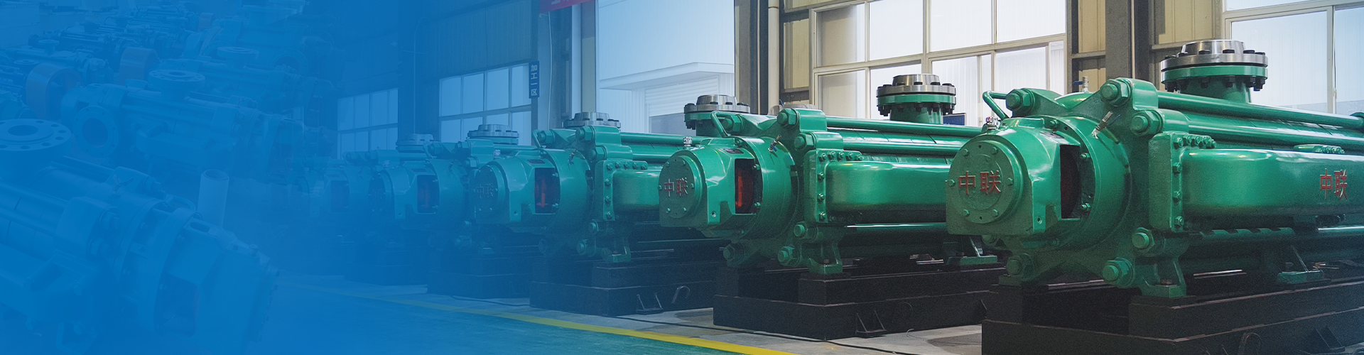
Having 26 series -312 varieties - over 1000 pump models
Focused on water pump research and development manufacturing for 36 years
Free training for operation and maintenance personnel/free installation guidance/free provision of installation drawings
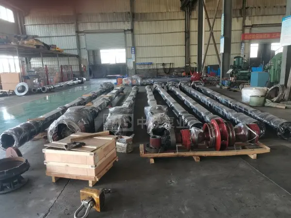


Seawater axial-flow pump
Traffic: 60–5100 m³/h
Head: 13~120m
Power: 5.5-1250kw
Shaft power: 3.9-1000kw
Rotational speed: 590-2950r/min
Efficiency: 70-85%
Price: 83,000 to 456,000
The seawater long-shaft pump is a new-generation vertical long-shaft pump that has been optimally designed on the basis of the original LC vertical long-shaft pump, with the primary goal of enhancing the pump’s safety, reliability, and performance. It is used for conveying seawater or other media containing corrosive substances.
Hotline:
Long-axis pump
Horizontal Single-Stage Fire Pump

Product Parameters
· Meaning of the model designation for seawater axial-flow pumps
200LCF-23A×2-LH
200——The pump outlet diameter is 200 mm.
LCF—Seawater Long-Axis Pump
23—When the impeller is not cut, the single-stage design head of the pump is 23 m (total pump head = single-stage head × number of impeller stages).
A—Impeller outer diameter cutting code
×2—The impeller has 2 stages (omitted when the stage number is 1).
L Submerged depth (Lw40m, unit: m)
H—Pump with protective casing (omit if no protective casing is used).
Note: The model formats for 100-caliber and 150-caliber pumps are 100LC50-20Ax2-L and 150LC140-15Ax2-L, respectively, where 50 and 140 represent the pump’s design-point flow rate. For vertical long-shaft pump models with diameters ranging from 200 to 1000 calibers, the flow-rate parameter is not included in the model format.
· Structural features of the seawater long-axis pump
1. The bearing assembly of the seawater axial-flow pump adopts a dual-ball-bearing structure. Above the original thrust bearing, a deep-groove ball bearing has been added to provide radial positioning for the entire rotor assembly, ensuring excellent balance of both axial and radial forces and thereby enhancing the pump’s operational stability and reliability.
2. The seawater axial-flow pump employs an advanced and rational bearing lubrication method—constant-oil-level metered thin-oil lubrication. The position of the bearing housing’s interface with the oil-level meter is determined through careful calculation. As long as the oil-level meter indicates the presence of oil, it means that the oil level within the bearing housing remains consistently at half the height of the thrust bearing’s balls, ensuring excellent lubrication performance. The deep-groove ball bearings located in the upper part of the bearing housing rely on the rotation of the journal (which features rectangular threaded grooves and radial oil-sliding holes) to fling oil onto the rolling elements of the upper bearing, thereby achieving splash lubrication.
3. Modular design of common components: We have categorized the common components across the entire product series. Currently, there are nearly eighty standard specifications and models of key common parts, including bearing components, packing components, intermediate guide bearing components, shaft assemblies, and intermediate pipe systems. This approach has significantly enhanced the interchangeability and quality of pump components, shortened the production cycle, and reduced product costs. Meanwhile, we have optimized and redesigned the existing shaft assembly so that the length of each individual shaft does not exceed 2 meters, ensuring even distribution of guide bearings and thereby reducing pump vibration.
4. The pump shaft coupling design has been improved by adopting a sleeve-type rigid coupling (comprising a coupling sleeve and a coupling joint). The inner bore of the coupling sleeve features a tapered structure—larger at the bottom and smaller at the top—for easy assembly and disassembly. The shaft section that mates with the coupling sleeve is chrome-plated to effectively prevent seizing. For the two connected shaft sections, the lower section is equipped with a step, while the upper section is fitted with an elastic retaining ring, which securely holds the coupling sleeve in place and prevents it from slipping off the shaft, thus avoiding damage to the pump.
5. The shaft connection points (couplings and coupling sleeves) of the seawater long-shaft pump are all designed at the upper end of each section’s guide bearing frame. The guide bearings can be installed from both the top and bottom directions. This design allows on-site assembly by using the guide bearing frames as support points, section by section, thereby avoiding installation and maintenance difficulties caused by insufficient plant height.
6. Three different lengths have been added to each shaft assembly to adjust the submersion depth. For order requirements involving different submersion depths, intermediate shaft combinations of varying lengths can be easily selected and used—this is extremely convenient.
7. The outer sleeve of the seawater axial-flow pump has been modified from an internal stop to an external stop. A specialized fixture (mandrel) is used for one-time clamping and machining, ensuring concentricity between the upper and lower stops and preventing eccentricity between the shaft and guide bearings caused by accumulated machining errors.
8. The water-guided bearing adopts a new type of PFC polymer material, which boasts significantly superior performance—such as wear resistance, dry-running resistance, high-temperature resistance, and corrosion resistance—compared to the guide bearing materials commonly used in the industry. This results in smoother, more reliable pump operation and an extended service life. Moreover, the guide bearing we use shows virtually no swelling even after being immersed for five months, making it exceptionally well-suited for vertical long-shaft pumps and greatly reducing the likelihood of shaft seizure.
9. The rotor undergoes dynamic balancing with an accuracy reaching the national standard level of G6.3, which is higher than the static balancing requirements typically imposed on vertical pumps in the industry. This helps reduce pump vibration.
10. The hydraulic models with poor performance were redesigned, thereby improving the pump’s efficiency.
11. Typically, the pump is equipped with an inner protective pipe (inner tube). When the medium being conveyed contains solid particles, it is essential to flush, lubricate, and cool the guide bearings by passing pressurized clean water at a pressure exceeding 2/3 of the rated head. If the pump is conveying a clean, ambient-temperature medium, the inner protective pipe can be omitted upon user request, allowing for dry-start operation.

·Material reference for seawater axial-flow pumps
Main parts | Seawater or corrosive media | |
Flared mouth | HT200Ni2Cr | 321/316L stainless steel |
Impeller | ZG1Cr18Ni9Ti | ZCuZn16Si4/316L stainless steel |
Sealing ring | HT200Ni2Cr | ZCuZn16Si4/316L stainless steel |
Guide vane body | HT200Ni2Cr | ZG00Cr17Ni14Mo2 |
Suction pipe, protective pipe | 1Cr18Ni9Ti | 00Cr17Ni14Mo2 |
axis | 1Cr18Ni9Ti | 00Cr17Ni14Mo2 |
Shaft sleeve | lCr17Ni2 | 1Cr17Ni2 |
Guide bearing | Polytetrafluoroethylene/Sealant/Rubber (NBR) | |
Guide bearing housing | HT200Ni2Cr | ZG00Cr17Ni14Mo2 |
Threaded and Sleeve Couplings | 1Cr17Ni2 | 1Cr17Ni2 |
Outflow bend pipe | 1Cr18Ni9Ti | 00Cr17Ni14Mo2 |
Motor mount | Q235-A | Q235-A |
· Maintenance and Servicing of Seawater Long-Axis Pumps
1. Pump disassembly
The disassembly of a seawater axial-flow pump is generally the reverse of the installation process. For all contact surfaces, including the end faces and stop collars of the drive shaft and the lift pipe, as well as the threaded external surfaces, use kerosene for cleaning and then apply rust-preventive oil.
2. Disassembly of the pump body
<1> Release the lower guide shroud;
<2> Use a rammer to strike the small end of the tapered sleeve from the impeller’s inlet, thereby loosening the fit between the tapered sleeve and the impeller; then remove the tapered sleeve and the impeller.
<3> Remove the next-level guide shell;
<4> Repeat steps 2 and 3 to remove all diffuser housings, impellers, and tapered sleeves.
After the pump body has been disassembled, inspect the parts for wear. If wear is severe, the parts should be replaced.
3. Repair
<1> After the pump body has been disassembled, inspect the impeller for wear. If the wear is severe, the impeller should be replaced; if the wear is only slight, you can sand down the contact surfaces and continue using it. Also, inspect the impeller sealing ring and, depending on the degree of wear, decide whether to replace it.
<2> If the conical surface where the guide vane shell mates with the impeller is worn, it should be re-aligned to ensure that the mating surfaces remain consistent with those of the impeller. Additionally, the flow passages in the guide vane shell should undergo necessary inspection and cleaning.
<3> If the impeller shaft has a chrome-plated area, it should be inspected. If the chrome coating has already flaked off, the shaft should be replaced.
<4> Inspect the guide bearings inside the flow guide casing and, based on their wear condition, determine whether they need to be replaced.
<5> Check whether the tapered sleeve is damaged; if it is, it should be replaced.
4. Periodic Maintenance
The maintenance cycle for water pumps is between six months and one year. After a pump has been in operation for one year, if the unit continues to run smoothly without significant vibration and the ammeter readings remain normal, the maintenance cycle may be appropriately extended—but not beyond three years. If the pump has been running for less than one year but the unit exhibits relatively intense vibration, it’s advisable to consider whether the guide bearings have prematurely failed. In such cases, the pump should be promptly shut down for inspection and damaged components replaced. Regularly check the sand content in the well; if the sand level is excessively high, the well should be cleaned.
· Common Faults and Troubleshooting Methods for Seawater Long-Axis Pumps
Types of faults | Cause of occurrence | Elimination method |
Motor overload | 1. The impeller and the sealing ring are rubbing against each other. | 1. Adjust the gap |
2. There is a foreign object inside the pump. | 2. Remove foreign objects | |
3. Bearing damage | 3. Replace the bearing | |
4. The packing is compressed too tightly. | 4. Properly loosen the packing. | |
5. Excessive rotational speed | 5. Check the voltage, frequency, and motor, and make adjustments as needed. | |
6. Operating beyond the specified range, running at high flow rates | 6. Close the outlet gate valve. | |
7. One phase of the power supply line is open-circuited, resulting in single-phase operation. | 7. Professional personnel inspect and repair. | |
Traffic reduction | 1. Excessive wear on the impeller seal ring | 1. Replace the impeller seal ring |
2. The dynamic water level inside the well has dropped significantly. | 2. Increase the number of impeller stages or replace the pump casing with one that has a higher head. | |
3. Impeller wear caused by improper clearance adjustment | 3. Replace the impeller | |
4. The inlet filter screen is blocked by foreign objects. | 4. Clean the filter screen | |
5. The threads connecting the diffuser casing are loose or leaking. | 5. Tighten the thread. | |
6. Leakage at the suction pipe connection. | 6. Check whether there are any signs of water leakage on the lift pipe section, and whether the end face of the bracket is smooth. | |
7. Incorrect steering | 7. Correct steering | |
8. Too low rotational speed | 8. Check the power supply to ensure it meets the requirements. | |
No water supply | 1. The dynamic water level is lower than the suction bellmouth. | 1. Increase the number of impellers and shafts required. If this results in a reduction in flow rate, under conditions where the power allows, increase the number of impeller stages or replace the pump casing. |
2. The transmission shaft has broken. | 2. Investigate the cause of the shaft failure and replace the transmission shaft. | |
3. The connection part of the lift pipe has cracked, causing significant water leakage. | 3. Study the causes of cracking and eliminate its defects. | |
Intense vibration | 1. During the installation and commissioning process, no water was introduced; vibration occurred before any water flowed out. | 1. Add pre-lubricating water |
2. Insufficient submergence depth leads to cavitation. | 2. Raise the suction water level or partially close the outlet gate valve. | |
3. The transmission shaft is misaligned or bent. | 3. Correct or replace the drive shaft. | |
4. Impeller imbalance | 4. Impeller static balance correction | |
5. Foundation bolts are loose. | 5. Tighten the anchor bolts. | |
6. Bearing damage | 6. Replace the bearing | |
7. The impact of the discharge pipeline | 7. Check and eliminate influencing factors. | |
At the stuffing box | 1. The filler has worn out. | 1. Increase filler content |
Too much leakage | 2. The filler is too hard or not compact enough. | 2. Replace the packing material, add another layer of packing material, or tighten the packing gland. |
3. Shaft oscillation and bending | 3. Correction axis | |
4. Due to the high sand content, the shaft or packing experiences excessive wear. | 4. Replace the shaft or the filling material and check the sand content inside the well. | |
Packing gland overheating | 1. The packing is compressed too tightly or the shaft is bent. | 1. Check the packing compression and installation condition. |
2. Insufficient or no water flow in the stuffing box. | 2. Loosened packing gland packing allows water to leak out. | |
Cannot stop the reversal. | 1. The reverse-flow vent hole is not clean. | 1. Clean the check pin and check hole. |
2. The anti-reverse ratchet is worn out. | 2. Replace the anti-reverse ratchet. |
· Technical Parameters of Seawater Long-Axis Pump
50LC/YLT-10 | 200LC/YLT-20 | 400LC/YLT-35 | 800LC/YLT-15 |
50LC/YLT2-20 | 200LC/YLT2-30 | 400LC/YLT2-40 | 800LC/YLT-20 |
50LC/YLT3-30 | 200LC/YLT2-40 | 400LC/YLT2-50 | 800LC/YLT-25 |
50LC/YLT4-40 | 200LC/YLT3-65 | 400LC/YLT2-60 | 900LC/YLT-4 |
50LC/YLT5-50 | 200LC/YLT4-90 | 500LC/YLT-4 | 900LC/YLT-6 |
50LC/YLT6-60 | 250LC/YLT-20 | 500LC/YLT-6 | 900LC/YLT-8 |
50LC/YLT7-70 | 250LC/YLT2-30 | 500LC/YLT-8 | 900LC/YLT-10 |
50LC/YLT8-80 | 250LC/YLT2-40 | 500LC/YLT-10 | 900LC/YLT-14 |
50LC/YLT9-90 | 250LC/YLT2-50 | 500LC/YLT-12 | 900LC/YLT-16 |
50LC/YLT10-100 | 250LC/YLT3-60 | 500LC/YLT-15 | 900LC/YLT-20 |
65LC/YLT-10 | 250LC/YLT3-75 | 500LC/YLT-20 | 900LC/YLT-25 |
65LC/YLT2-20 | 250LC/YLT4-95 | 500LC/YLT-25 | 1000LC/YLT-4 |
65LC/YLT3-30 | 300LC/YLT-6 | 500LC/YLT-30 | 1000LC/YLT-7 |
65LC/YLT4-40 | 300LC/YLT-8 | 500LC/YLT-35 | 1000LC/YLT-9 |
65LC/YLT5-50 | 300LC/YLT-10 | 500LC/YLT-40 | 1000LC/YLT-10 |
65LC/YLT6-60 | 300LC/YLT-15 | 600LC/YLT-4 | 1000LC/YLT-13 |
65LC/YLT7-70 | 300LC/YLT-20 | 600LC/YLT-6 | 1000LC/YLT-16 |
65LC/YLT8-80 | 300LC/YLT2-30 | 600LC/YLT-8 | 1000LC/YLT-18 |
65LC/YLT9-90 | 300LC/YLT2-40 | 600LC/YLT-10 | 1000LC/YLT-20 |
65LC/YLT10-100 | 300LC/YLT3-60 | 600LC/YLT-12 | 1200LC/YLT-4 |
80LC/YLT-15 | 300LC/YLT4-80 | 600LC/YLT-15 | 1200LC/YLT-6 |
80LC/YLT2-30 | 350LC/YLT-4 | 600LC/YLT-20 | 1200LC/YLT-9 |
80LC/YLT3-45 | 350LC/YLT-6 | 600LC/YLT-25 | 1200LC/YLT-12 |
80LC/YLT4-60 | 350LC/YLT-8 | 600LC/YLT-30 | 1200LC/YLT-14 |
80LC/YLT5-75 | 350LC/YLT-10 | 600LC/YLT-35 | 1200LC/YLT-16 |
80LC/YLT6-90 | 350LC/YLT-15 | 600LC/YLT-40 | 1200LC/YLT-18 |
80LC/YLT7-105 | 350LC/YLT-20 | 700LC/YLT-4 | 1200LC/YLT-20 |
100LC/YLT-15 | 350LC/YLT2-30 | 700LC/YLT-6 | 1200LC/YLT-24 |
100LC/YLT-30 | 350LC/YLT2-40 | 700LC/YLT-8 | 1400LC/YLT-14 |
100LC/YLT2-60 | 350LC/YLT3-60 | 700LC/YLT-10 | 1400LC/YLT-60 |
100LC/YLT3-90 | 350LC/YLT4-80 | 700LC/YLT-12 | 1400LC/YLT-60A |
100LC/YLT4-120 | 400LC/YLT-4 | 700LC/YLT-15 | 1400LC/YLT-60B |
150LC/YLT-20 | 400LC/YLT-6 | 700LC/YLT-20 | 1400LC/YLT-10 |
150LC/YLT2-30 | 400LC/YLT-8 | 700LC/YLT-25 | 1600LC/YLT-12 |
150LC/YLT2-40 | 400LC/YLT-10 | 700LC/YLT-30 | 1600LC/YLT-13.5 |
150LC/YLT3-60 | 400LC/YLT-13 | 800LC/YLT-4 | 1600LC/YLT-14.6 |
150LC/YLT4-80 | 400LC/YLT-16 | 800LC/YLT-6 | 1600LC/YLT-20 |
150LC/YLT5-100 | 400LC/YLT-20 | 800LC/YLT-8 | 1600LC/YLT-19 |
150LC/YLT6-120 | 400LC/YLT-25 | 800LC/YLT-10 | 1800LC/YLT-34 |
200LC/YLT-15 | 400LC/YLT-30 | 800LC/YLT-12 | 1800LC/YLT-34A |
Friendly reminder: Click on the model above to view detailed specifications, graphs, and other information.
Why choose us?
Changsha Zhonghlian Pump Industry Co., Ltd. was founded in 1989 and was independently established after the restructuring of Changsha Water Pump Factory. It is a comprehensive national high-tech enterprise integrating design, research and development, manufacturing, and service. The company was listed on the Hunan Provincial Equity Exchange on December 31, 2019, with the abbreviation "Zhonghlian Pump Industry" and the equity code: 600275HN. It is currently a key backbone enterprise in China's centrifugal pump industry and one of the major professional manufacturers of multi-stage pumps in the country. The headquarters is located in Changsha City, Hunan Province, a historical and cultural city in China.
Square meters of land area
100% factory pass rate
Square meters of land area
100% factory pass rate
Q
What is your typical delivery time?
A
Models in stock can be shipped the next day at the latest. All others are custom-made, with lead times generally ranging from 7 to 90 days depending on the product size and project specifics. Please contact our sales manager for details: 0731-88632200 。
Q
Do you have centrifugal pumps in stock?
A
Centrifugal pumps come in numerous models and configurations. Except for a small number of high-volume, standard models that are in stock, the vast majority are not stocked and are customized products. We need to select a pump based on your site's flow rate, head, media temperature, pH value, and installation conditions, etc., to determine the pump model and configuration before we can submit an order to the factory for production.
Q
What information should I provide when requesting a quote?
A
Generally, to obtain an accurate quotation, we recommend providing us with the following information: pump flow rate, head, on-site operating voltage and frequency, temperature, pH value, and solid particle content of the fluid being conveyed, and on-site installation conditions (horizontal or vertical installation), etc.
If you are not sure, don't worry, our business managers will assist you in determining this.
Q
What products do you mainly produce?
A
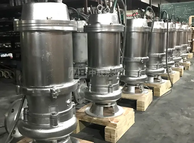
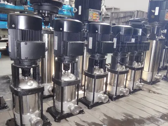
Zhonglian Pump Industry manufactures various large industrial centrifugal pumps. Main products include: self-balancing multi-stage pumps, multi-stage centrifugal pumps, single-stage centrifugal pumps, split-case pumps, chemical pumps, submersible pumps, pipeline pumps, long-shaft pumps, condensate pumps, etc.
Q
Why is it so slow to get a price quote?
A
Because centrifugal pumps are non-standard customized products with many models, the price range is also very large. Even for the same model, the price difference is also very large due to different materials and configurations. Taking the most common water pump accessory—the impeller—as an example, the price of a stainless steel impeller is several times that of a cast iron impeller. Therefore, we need to clarify the relevant information to give you an accurate price. Normally, if you provide relatively comprehensive information, we can quote within 5 minutes.
Previous Page
Previous Page

Product message
Contact our team promptly; we are happy to help you.
*Note: Please fill in the information accurately and keep the communication open. We will contact you as soon as possible.

Hotline:
+86 0731-88632200
Export Trade/Technical Support:
+86 153-4831-2290
Head Office Email:
zoomlian@yeah.net
No. 210, Huanbao Zhong Road, Yuhua District, Changsha City, Hunan Province, Leowoju Wisdom Valley Building B, 8th Floor
Quick Navigation


Hot Products
Online Consultation
Powered by:www.300.cn Changsha SEO