

-
Product
-
-
Service Policy
-
-
Blog
-
Join Us
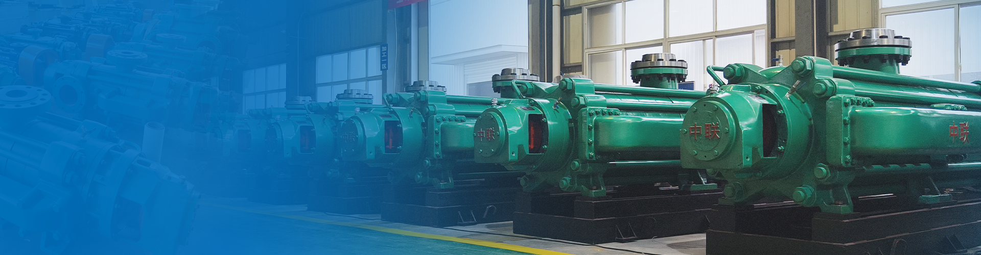
Having 26 series -312 varieties - over 1000 pump models
Focused on water pump research and development manufacturing for 36 years
Free training for operation and maintenance personnel/free installation guidance/free provision of installation drawings
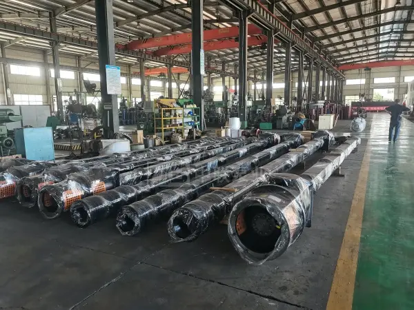


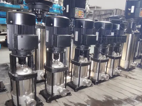
Sewage long-axis pump
Traffic: 15–5,500 m³/h
Head: 10-300m
Power: 4.5-1200kw
Shaft power: 3.2-1600kw
Rotational speed: 590-2950r/min
Efficiency: 70-85%
Price: 28,500 to 196,000
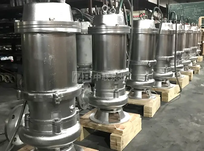
The submersible long-shaft sewage pump, also known as the long-shaft sewage discharge pump, is a type of working pump used for wastewater discharge. It can be operated under the following conditions: ① When operating, the submersible long-shaft sewage pump must be ensured to have a sufficient submergence depth; refer to the pump’s installation dimension drawing for the minimum submergence depth requirement.
Hotline:
Long-axis pump
Horizontal Single-Stage Fire Pump

Product Parameters
[Product Advantages]
1. The sewage long-axis pump occupies a small footprint and can be designed with multiple stages to accommodate higher head requirements.
2. The sewage long-axis pump is a dry-type pump, which is safer and more reliable than submersible pumps.
3. No priming is required; it can be started at any time.
4. It features a unique sand-discharging structure that enables it to handle water containing sand.
5. Metal molds cast using a full machining center feature a beautiful appearance and smooth flow channels.
[Model Meaning]
200LCW-23A×2-LH
200——The pump outlet diameter is 200 mm.
LCW—Vertical Long-Shaft Sewage Pump
23—When the impeller is not cut, the single-stage design head of the pump is 23 m (total pump head = single-stage head × number of impeller stages).
A—Impeller outer diameter cutting code
×2—The impeller has 2 stages (omitted when the stage number is 1).
L Submerged depth (Lw40m, unit: m)
H—Pump with protective casing (omit if no protective casing is used).
Note: The model formats for 100-caliber and 150-caliber pumps are 100LCW50-20Ax2-L and 150LCW140-15Ax2-L, respectively, where 50 and 140 represent the pump’s design-point flow rate. For vertical long-shaft pump models with diameters ranging from 200 to 1000, the flow-rate parameter is not included in the model format.
[Parts Material List]
Main parts | Clear water | Wastewater | Seawater | |
I | II | III | IV | |
Flared mouth | HT200 | HT20/QT400-18 | HT200Ni2Cr | 321/316L stainless steel |
Impeller | HT200 | QT400-18/Cast Steel/ZG1Cr13Ni1 | ZG1Cr18Ni9Ti | ZCuZn16Si4/316L stainless steel |
Sealing ring | HT200 | QT400-18/2Cr13 | HT200Ni2Cr | ZCuZn16Si4/316L stainless steel |
Guide vane body | HT200 | QT400-18/Cast Steel | HT200Ni2Cr | ZG00Cr17Ni14Mo2 |
Suction pipe, protective pipe | Q235-A | Q235-A | 1Cr18Ni9Ti | 00Cr17Ni14Mo2 |
axis | 45/2Cr13 | 45/2Cr13 | 1Cr18Ni9Ti | 00Cr17Ni14Mo2 |
Shaft sleeve | 2Cr13 | 2Cr13 | lCr17Ni2 | 1Cr17Ni2 |
Guide bearing | Polytetrafluoroethylene/Sealant/Rubber (NBR) | |||
Guide bearing housing | HT200 | HT200/QT400-18 | HT200Ni2Cr | ZG00Cr17Ni14Mo2 |
Threaded and Sleeve Couplings | 45/2Cr13 | 40Cr/2Cr13 | 1Cr17Ni2 | 1Cr17Ni2 |
Outflow bend pipe | Q235-A | Q235-A | 1Cr18Ni9Ti | 00Cr17Ni14Mo2 |
Motor mount | Q235-A | Q235-A | Q235-A | Q235-A |
[Drive Type]
The sewage long-axis pump comes in four drive types:
ⅰ) Driven directly by a standard vertical motor;
ⅱ) Directly driven by a vertical hollow-shaft motor;
ⅲ) Driven by a diesel engine or steam turbine via a right-angle gearbox for speed variation;
ⅳ) It is driven by a horizontal motor via a right-angle gearbox for speed variation.
[Structural Description]
The sewage long-axis pump equipment mainly consists of three components: the pump body assembly, the lift pipe assembly, and the pump base assembly. The first two components are located underground, while the pump base assembly is situated above ground.
ⅰ) Pump body components
The main components of the pump body include: a filter screen, an impeller, a sealing ring, a tapered sleeve, an intake bellmouth, a guide vane body, a guide bearing, and an impeller shaft, among other parts.
The suction bellmouth is connected to the guide vane body and the guide vane body itself via flanges. The impeller is secured using a tapered sleeve.
ⅱ) Suction pipe components
The submersible pump assembly consists of components such as the submersible pump, transmission shaft, guide bearing housing, guide bearing, and coupling.
Flange connections are used between the lift pipes; couplings come in two types: threaded couplings and sleeve couplings, with threaded couplings being the more commonly used.
ⅲ) Pump base component
The pump base assembly mainly includes the discharge elbow and packing device. When driven by a conventional vertical motor, it also features components such as a motor support, thrust bearing assembly, anti-reverse mechanism, and pump-motor coupling.
The entire pump base assembly is secured to the foundation by multiple anchor bolts.
[Structural Diagram]


[Installation Instructions]
Before installation, be sure to inspect the sewage long-axis pump equipment.
1. Count the parts and check whether any are missing or damaged.
2. Check whether the tightness of all assembled fasteners is appropriate.
3. Rotate the pump shaft by hand—it should turn smoothly.
[Installation Steps]
<1> Install the filter screen;
<2> Connect the lower transmission shaft to the impeller shaft using a coupling.
<3> Secure the lower lifting pipe to the uppermost guide casing using bolts.
<4> After lifting the assembled components mentioned above, carefully lower them into the well and then use the flange’s protruding rim to secure them onto the square timbers on the well platform.
<5> Install the guide bearing assembly, the preceding section of the transmission shaft, and the lift pipe;
<6> Repeat steps 4 and 5 until all transmission shafts and lift pipes have been installed;
<7> Remove the packing from the packing chamber of the outlet bend pipe. Lift the outlet bend pipe so that the upper shaft passes through the hole in the packing chamber. Connect the rising water pipe to the outlet bend pipe, then slowly lower it until the outlet bend pipe rests on the foundation.
<8> Install the packing and tighten the packing gland;
<9> Depending on the drive method, the following steps are divided into three cases:
ⅰ) Standard vertical motor drive
First, install the motor bracket onto the upper part of the outlet bend pipe. Next, secure the thrust bearing housing to the motor bracket using bolts. Place the thrust bearing into the thrust bearing housing. After fitting the key onto the upper shaft, slide the bearing bushing over the shaft. Then, install the anti-reverse ratchet mechanism. Finally, insert the pump coupling and tighten it with the small round nut (adjusting nut).
ⅱ) Hollow-shaft motor drive
Remove the waterproof cover from the top of the motor, then lift the motor so that the upper shaft passes through the motor’s hollow rotor. Install the motor onto the outlet bend pipe and secure it with the adjusting nut.
ⅲ) Driven by a right-angle gearbox
The installation method is similar to that of a hollow-shaft motor drive.
<10> Adjust the axial clearance by turning the adjusting nut.
[Pre-Operation Preparations]
1. Adjustment of axial clearance
Before commissioning the pump, it is essential to adjust the axial clearance between the diffuser casing and the impeller so that, during operation, the impeller neither rubs against the diffuser casing nor compromises performance requirements. This pump uses adjusting nuts to regulate the axial clearance; the main steps are as follows:
For a newly installed pump that often cannot rotate, adjust the adjusting nut until the shaft just begins to turn. Use the position of the nut at this point as the initial adjustment setting.
The adjustment amount for the axial clearance is half of the pump’s total axial play. Typically, the total axial play ranges from 6 to 8 mm, meaning the usual adjustment range is 3 to 4 mm. To determine the number of turns required for the adjusting nut, simply divide the adjustment amount by the pitch of the adjusting nut’s threads. For example, if a pump has a total axial play of 6 mm and the adjusting nut has a thread pitch of 1.5 mm, you should turn the adjusting nut two full turns from the initial adjustment position. After completing the adjustment, tighten the second small round nut or insert a locking pin to secure the adjustment.
After adjusting according to the method described above, start the pump and observe whether the ammeter reading exceeds the rated current of the motor. If the motor’s operating current is excessively high (exceeding 110% of the rated current), it indicates that the clearance is too small; stop the pump and increase the clearance slightly. For newly installed pumps, it is recommended to adjust the clearance again after the pump has been running for 20 minutes. For deep wells containing a small amount of silt or sand, the axial clearance should be increased—our pump recommends turning an additional (1/2 to 1) full turn beyond the original adjustment position—to reduce wear on the impeller during operation.
2. Pre-lubrication
<1> Before starting the submersible pump, clean water should be introduced into the lubrication water holes of the pump housing to ensure that the shaft and bearings are pre-lubricated.
<2> In areas without access to tap water, a pre-wetting tank with a volume of approximately 0.2 m³ should be installed. The motor may only be started after most of the water from the tank has flowed into the deep-well pump.
<3> At locations where a water tank is not yet available, water can be temporarily supplied using buckets, but the volume of water filled should not be less than 0.1 m³.
3. Pre-start inspection
Before starting the sewage long-axis pump, at least the following items should be checked: foundation installation, axial clearance adjustment, pre-tightening degree of the packing gland, pre-lubrication, motor lubricant oil, electrical equipment, and the flexibility of the pump rotor’s rotation. The pump may only be started once the checked items meet the requirements.
[Startup and Operation]
It is recommended that submersible sewage pumps use reduced-voltage starting. The valve must be opened when starting the pump. After using a deep-well pump, it is essential to regularly measure both the static and dynamic water levels in the well. Each start-up requires pre-lubrication. When the motor stops, check the oil level in the lubrication system; if the oil level is insufficient, add more oil as needed.
[Technical Parameters]
50LC/YLT-10 | 200LC/YLT-20 | 400LC/YLT-35 | 800LC/YLT-15 |
50LC/YLT2-20 | 200LC/YLT2-30 | 400LC/YLT2-40 | 800LC/YLT-20 |
50LC/YLT3-30 | 200LC/YLT2-40 | 400LC/YLT2-50 | 800LC/YLT-25 |
50LC/YLT4-40 | 200LC/YLT3-65 | 400LC/YLT2-60 | 900LC/YLT-4 |
50LC/YLT5-50 | 200LC/YLT4-90 | 500LC/YLT-4 | 900LC/YLT-6 |
50LC/YLT6-60 | 250LC/YLT-20 | 500LC/YLT-6 | 900LC/YLT-8 |
50LC/YLT7-70 | 250LC/YLT2-30 | 500LC/YLT-8 | 900LC/YLT-10 |
50LC/YLT8-80 | 250LC/YLT2-40 | 500LC/YLT-10 | 900LC/YLT-14 |
50LC/YLT9-90 | 250LC/YLT2-50 | 500LC/YLT-12 | 900LC/YLT-16 |
50LC/YLT10-100 | 250LC/YLT3-60 | 500LC/YLT-15 | 900LC/YLT-20 |
65LC/YLT-10 | 250LC/YLT3-75 | 500LC/YLT-20 | 900LC/YLT-25 |
65LC/YLT2-20 | 250LC/YLT4-95 | 500LC/YLT-25 | 1000LC/YLT-4 |
65LC/YLT3-30 | 300LC/YLT-6 | 500LC/YLT-30 | 1000LC/YLT-7 |
65LC/YLT4-40 | 300LC/YLT-8 | 500LC/YLT-35 | 1000LC/YLT-9 |
65LC/YLT5-50 | 300LC/YLT-10 | 500LC/YLT-40 | 1000LC/YLT-10 |
65LC/YLT6-60 | 300LC/YLT-15 | 600LC/YLT-4 | 1000LC/YLT-13 |
65LC/YLT7-70 | 300LC/YLT-20 | 600LC/YLT-6 | 1000LC/YLT-16 |
65LC/YLT8-80 | 300LC/YLT2-30 | 600LC/YLT-8 | 1000LC/YLT-18 |
65LC/YLT9-90 | 300LC/YLT2-40 | 600LC/YLT-10 | 1000LC/YLT-20 |
65LC/YLT10-100 | 300LC/YLT3-60 | 600LC/YLT-12 | 1200LC/YLT-4 |
80LC/YLT-15 | 300LC/YLT4-80 | 600LC/YLT-15 | 1200LC/YLT-6 |
80LC/YLT2-30 | 350LC/YLT-4 | 600LC/YLT-20 | 1200LC/YLT-9 |
80LC/YLT3-45 | 350LC/YLT-6 | 600LC/YLT-25 | 1200LC/YLT-12 |
80LC/YLT4-60 | 350LC/YLT-8 | 600LC/YLT-30 | 1200LC/YLT-14 |
80LC/YLT5-75 | 350LC/YLT-10 | 600LC/YLT-35 | 1200LC/YLT-16 |
80LC/YLT6-90 | 350LC/YLT-15 | 600LC/YLT-40 | 1200LC/YLT-18 |
80LC/YLT7-105 | 350LC/YLT-20 | 700LC/YLT-4 | 1200LC/YLT-20 |
100LC/YLT-15 | 350LC/YLT2-30 | 700LC/YLT-6 | 1200LC/YLT-24 |
100LC/YLT-30 | 350LC/YLT2-40 | 700LC/YLT-8 | 1400LC/YLT-14 |
100LC/YLT2-60 | 350LC/YLT3-60 | 700LC/YLT-10 | 1400LC/YLT-60 |
100LC/YLT3-90 | 350LC/YLT4-80 | 700LC/YLT-12 | 1400LC/YLT-60A |
100LC/YLT4-120 | 400LC/YLT-4 | 700LC/YLT-15 | 1400LC/YLT-60B |
150LC/YLT-20 | 400LC/YLT-6 | 700LC/YLT-20 | 1400LC/YLT-10 |
150LC/YLT2-30 | 400LC/YLT-8 | 700LC/YLT-25 | 1600LC/YLT-12 |
150LC/YLT2-40 | 400LC/YLT-10 | 700LC/YLT-30 | 1600LC/YLT-13.5 |
150LC/YLT3-60 | 400LC/YLT-13 | 800LC/YLT-4 | 1600LC/YLT-14.6 |
150LC/YLT4-80 | 400LC/YLT-16 | 800LC/YLT-6 | 1600LC/YLT-20 |
150LC/YLT5-100 | 400LC/YLT-20 | 800LC/YLT-8 | 1600LC/YLT-19 |
150LC/YLT6-120 | 400LC/YLT-25 | 800LC/YLT-10 | 1800LC/YLT-34 |
200LC/YLT-15 | 400LC/YLT-30 | 800LC/YLT-12 | 1800LC/YLT-34A |
Friendly reminder: Click on the model above to view detailed specifications, graphs, and other information.
Why choose us?
Changsha Zhonghlian Pump Industry Co., Ltd. was founded in 1989 and was independently established after the restructuring of Changsha Water Pump Factory. It is a comprehensive national high-tech enterprise integrating design, research and development, manufacturing, and service. The company was listed on the Hunan Provincial Equity Exchange on December 31, 2019, with the abbreviation "Zhonghlian Pump Industry" and the equity code: 600275HN. It is currently a key backbone enterprise in China's centrifugal pump industry and one of the major professional manufacturers of multi-stage pumps in the country. The headquarters is located in Changsha City, Hunan Province, a historical and cultural city in China.
Square meters of land area
100% factory pass rate
Square meters of land area
100% factory pass rate
Q
What is your typical delivery time?
A
Models in stock can be shipped the next day at the latest. All others are custom-made, with lead times generally ranging from 7 to 90 days depending on the product size and project specifics. Please contact our sales manager for details: 0731-88632200 。
Q
Do you have centrifugal pumps in stock?
A
Centrifugal pumps come in numerous models and configurations. Except for a small number of high-volume, standard models that are in stock, the vast majority are not stocked and are customized products. We need to select a pump based on your site's flow rate, head, media temperature, pH value, and installation conditions, etc., to determine the pump model and configuration before we can submit an order to the factory for production.
Q
What information should I provide when requesting a quote?
A
Generally, to obtain an accurate quotation, we recommend providing us with the following information: pump flow rate, head, on-site operating voltage and frequency, temperature, pH value, and solid particle content of the fluid being conveyed, and on-site installation conditions (horizontal or vertical installation), etc.
If you are not sure, don't worry, our business managers will assist you in determining this.
Q
What products do you mainly produce?
A
Zhonglian Pump Industry manufactures various large industrial centrifugal pumps. Main products include: self-balancing multi-stage pumps, multi-stage centrifugal pumps, single-stage centrifugal pumps, split-case pumps, chemical pumps, submersible pumps, pipeline pumps, long-shaft pumps, condensate pumps, etc.
Q
Why is it so slow to get a price quote?
A
Because centrifugal pumps are non-standard customized products with many models, the price range is also very large. Even for the same model, the price difference is also very large due to different materials and configurations. Taking the most common water pump accessory—the impeller—as an example, the price of a stainless steel impeller is several times that of a cast iron impeller. Therefore, we need to clarify the relevant information to give you an accurate price. Normally, if you provide relatively comprehensive information, we can quote within 5 minutes.
Previous Page
Next Page
Previous Page
Next Page
Product message
Contact our team promptly; we are happy to help you.
*Note: Please fill in the information accurately and keep the communication open. We will contact you as soon as possible.

Hotline:
+86 0731-88632200
Export Trade/Technical Support:
+86 153-4831-2290
Head Office Email:
zoomlian@yeah.net
No. 210, Huanbao Zhong Road, Yuhua District, Changsha City, Hunan Province, Leowoju Wisdom Valley Building B, 8th Floor
Quick Navigation


Hot Products
Online Consultation
Powered by:www.300.cn Changsha SEO