

-
Product
-
-
Service Policy
-
-
Blog
-
Join Us
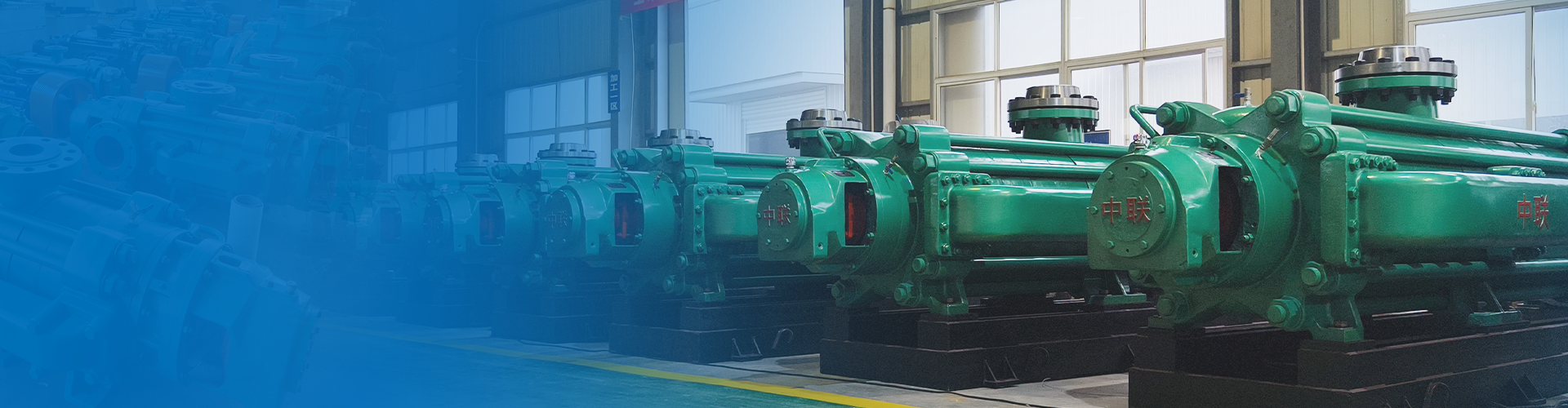
Having 26 series -312 varieties - over 1000 pump models
Focused on water pump research and development manufacturing for 36 years
Free training for operation and maintenance personnel/free installation guidance/free provision of installation drawings
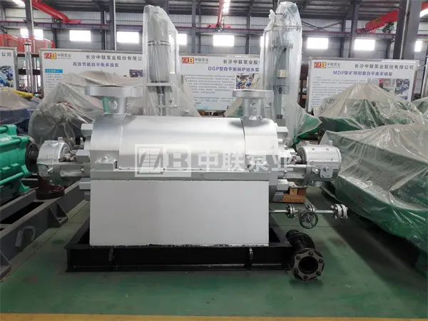


DG-type Sub-high-pressure Boiler Feed Pump (BB4)
Flow rate: 35–580 m³/h
Head: 270–2150 m
Power: 4–4500 kW
Efficiency: 42%-84%
Pump weight: 78–1963 kg
Cavitation margin: 2.0–7.0 m
Price: 0.81–168,000
Suitable for conveying clear water with a medium temperature ranging from -20℃ to 160℃ (with a maximum medium pressure not exceeding 105℃), or non-corrosive liquids whose physical and chemical properties are similar to those of water. The pump inlet pressure shall not exceed 0.59 MPa (6 kgf/cm²). This pump is widely used for boiler feedwater in industries such as power plants, metallurgy, and heating systems, and is also suitable for unit-based and main-pipeline-based systems in power plants of various capacities.
Hotline:
Multistage pump
Horizontal Single-Stage Fire Pump
Product Overview
The DG-type sub-high-pressure boiler feedwater pump is suitable for conveying clean water with a medium temperature ranging from -20℃ to 160℃ (with a medium pressure not exceeding 105℃), or non-corrosive liquids whose physicochemical properties are similar to those of water. The pump's inlet pressure must not exceed 0.59 MPa (6 kgf/cm²). This pump is widely used in boiler feedwater systems in industries such as power plants, metallurgy, and heating systems, and is also applicable to unit-based and main-pipeline-based feedwater systems for power plant units of various capacities. Its maximum head can reach up to 1,800 meters. As a high-pressure boiler feedwater pump or for other high-pressure water supply applications, the DG-type sub-high-pressure boiler feedwater pump is an efficient and energy-saving product specifically designed to replace and upgrade existing industrial steam boilers. It is suitable not only for medium- and low-pressure boiler feedwater systems but also for high-head water transmission in factories and urban areas.

↑DG280-65×6 Series Sub-high-pressure Boiler Feed Pump↑
The DG-type high-pressure boiler feed pump is a single-suction, multistage sectional centrifugal pump, belonging to the series of high-pressure boiler pumps with multiple stages. The pump casing can be axially disassembled at the shaft centerline. For the DG85-80×8 model, the suction port is oriented vertically upward, and the discharge port is also oriented vertically upward, perpendicular to the shaft centerline. When viewed from the drive end, the pump rotates clockwise; however, it can also be manufactured to rotate counterclockwise upon customer request. Customers may specify this preference when placing their order.
Model Description for DG-Type Subhigh-Pressure Boiler Feed Pumps
Model example: DG45-80×6
DG—Single-suction multistage high-pressure boiler feed pump
45——Pump design point flow rate
80——Single-stage head of the pump
6——Number of pump stages
Structural Features of DG-Type Sub-High-Pressure Boiler Feed Pumps

Bearing Balancing: The rotor of the DG-type high-pressure boiler pump is supported by rolling bearings located at both ends of the pump shaft. Lubrication is provided by thin oil, and cooling is achieved through circulating water. Axial thrust of the rotor is automatically balanced by a balance disc. The balanced return water flows back to the pump suction section via the balanced return pipe. The rotor of the DG-type sub-high-pressure pump is supported by sliding bearings located at both ends of the pump shaft. Lubrication is provided by thin oil, and cooling is achieved through circulating water. Axial thrust of the rotor is balanced by a balance disc. A return pipe is installed between the balance chamber and the front section. The rotor of the DG-type high-pressure boiler pump is supported by sliding bearings located at both ends of the pump. The bearings are forcibly lubricated, and the pump itself is equipped with an oil system. Axial thrust of the rotor is balanced by a balance disc, and a thrust bearing is also provided to accommodate any residual axial forces arising from changes in operating conditions. A return pipe is installed between the balance chamber body and the suction pipe.
Drive: The medium-pressure and sub-high-pressure multistage pumps are driven by electric motors via flexible couplings. When viewed from the drive direction, the pump rotates clockwise. The high-pressure pumps are also driven by electric motors via flexible couplings; depending on user requirements, they can be equipped with gear couplings, diaphragm couplings, or hydraulic couplers. The prime mover can be either a small steam turbine or an electric motor. When viewed from the drive direction, the pump rotates clockwise. The boiler feedwater pump’s pump body and pump cover together form the impeller’s working chamber. On the inlet and outlet flanges, there are threaded holes for installing vacuum gauges and pressure gauges. At the lower part of the pump body, there is a threaded hole for draining residual water.
The impeller is a single-suction, closed-type design. A balance disc is provided to counterbalance most of the axial forces, while a thrust bearing is installed to accommodate any remaining minor axial thrust. The arrangement of the bearings ensures that the shaft remains in a stable, tensioned state. Before assembly, each impeller must undergo rigorous static balancing verification to guarantee smooth operation.
The pump shaft is supported by two Babbitt alloy sliding bearings, which are housed in bearing housings within the pump suspension and lubricated with thin oil.
A sealing ring is installed on the pump body, which can enhance the pump’s volumetric efficiency. On the other hand, it can also prevent high-pressure water from flowing back into the suction chamber and disrupting the inflow flow field, thereby ensuring the pump’s reliable suction performance.
The shaft seal is typically a soft packing seal. During pump operation, a small amount of medium can be directed to the stuffing box, or external cooling and lubricating water can be supplied to serve both as a water seal and for cooling and lubrication. Upon user request, the packing seal can be replaced with a mechanical seal.
Material of Main Components for DG-Type Sub-High-Pressure Boiler Feed Pumps
| ● Inlet and outlet sections: ZG230-450 | ● Middle section: ZG230-450 | ● Guide vanes: QT450 |
| ● Impeller: QT450 | ● Spindle: 40Cr | ● Seal ring: QT450 |
| ● Bushing: HT250 | ● Balance disc: ZG2Cr13 | ● Balance ring: tin bronze |
Friendly reminder: Users can communicate with Zoomlion Pump Industry’s technical staff to obtain a reasonable configuration based on the site conditions and their specific requirements.
Installation Steps for DG-Type Subhigh-Pressure Boiler Feed Pumps
1. Preparatory work
Before assembly, all pump parts—especially the precision-machined surfaces that fit together—must be thoroughly cleaned.
Count all the parts and classify and number them according to the assembly sequence.
2. Assembly of pump components
Pay attention to installing the middle sealing ring properly to prevent it from falling off.
Pay attention to aligning the guide vane anti-rotation pin correctly.
Tighten the through-bolt nuts on the pump body symmetrically to maintain proper tightening force. If the nuts are too loose, leakage may occur at the middle joint surface; if they are too tight, the stator components may become deformed. During assembly, the torque of the wrench should be approximately 5,550 newton-meters. Tighten the through bolts symmetrically.
After the shaft is basically tightened, use a dial indicator to check that the parallelism between the front and rear sections should be ≤0.1 mm. 1.3 Measure the total axial runout of the rotor; it must meet the requirements specified in the drawings.
Install the front cover, the low-pressure end cover bearing, and the lower bearing shell, then lift the shaft into the center position.
Use dedicated lifting tools and a dial indicator to check the runout of the balance sleeve end face; it should meet the requirements specified in the assembly drawing.
Assemble the rotor components and tighten the lock nuts. The measured axial clearance after installing the balance disc shall meet the requirements specified in the general assembly drawing.
When installing the end caps, tail cap, bearing housing, and the top and side clearances of the bearing bushings, the values must conform to the specified requirements for bearing bushing quality.
Adjust the centers of the bearing shells on both sides, and after adjustment, tighten the adjusting nuts.
3. Assemble the thrust bearing
For the assembly of thrust bearing components, scrape and lap the babbitt bearings according to the requirements for bearing components. During assembly, the thrust pads should rotate freely. 1.9.2 After installing the thrust bearing, the axial clearance between the balance disc and the balance sleeve shall be within the range of 0.04 to 0.08 mm as specified in the general assembly drawing. The clearance adjustment shall be achieved using adjusting rings.
After adjusting the clearance, install the thrust bearing and thrust disc, then tighten the lock nut.
The pump body and pump cover form the working chamber for the impeller. On the inlet and outlet flanges, there are threaded holes for installing vacuum gauges and pressure gauges. At the lower part of the pump body, there is a threaded hole for draining residual water.
The impeller is a single-suction, closed-type design. A balance disc is provided to counterbalance most of the axial forces, while a thrust bearing is installed to accommodate any remaining minor axial thrust. The arrangement of the bearings ensures that the shaft remains in a stable, tensioned state. Before assembly, each impeller must undergo rigorous static balancing verification to guarantee smooth operation.
The pump shaft is supported by two Babbitt alloy sliding bearings, which are housed in bearing housings within the pump suspension and lubricated with thin oil.
A sealing ring is installed on the pump body, which can enhance the pump’s volumetric efficiency. On the other hand, it can also prevent high-pressure water from flowing back into the suction chamber and disrupting the inflow flow field, thereby ensuring the pump’s reliable suction performance.
The shaft seal is typically a soft packing seal. During pump operation, a small amount of medium can be directed to the stuffing box, or external cooling and lubricating water can be supplied to serve both as a water seal and for cooling and lubrication. Upon user request, the packing seal can be replaced with a mechanical seal.
The clearance between the thrust bearing housing and the thrust disc is adjusted using shims to ensure compliance with the total assembly drawing’s requirements for the thrust bearing clearance.
Operating Instructions for DG Type Subhigh-Pressure Boiler Feed Pumps
I. Start
Before starting the pump, rotate the pump rotor to check whether it moves freely.
Check whether the motor rotation direction is consistent with the pump rotation direction.
Open the pump suction valve, close the gate valve on the pump discharge pipeline and the pressure gauge cock, so that the pump is completely filled with liquid, or use a vacuum system to remove air from the suction pipe and the pump itself.
Check the tightness of the bolts connecting the pump and motor, as well as the safety conditions around the pump, to ensure that the pump is in a ready-to-start condition.
Start the motor. Once the pump is running normally, open the pressure gauge cock and gradually open the pump outlet gate valve until the pressure gauge pointer reaches the desired pressure (control the pump’s head according to the reading on the outlet pressure gauge).
II. Operation
This pump uses an internal balancing mechanism within the pump to counteract axial forces. The balancing device features a discharge of balancing fluid, which is routed via a balancing water pipe to the suction section, or alternatively, a short pipe can be designed outside the balancing chamber, through which the balancing fluid flows outward from the pump. To ensure normal pump operation, the balancing water pipe must never be blocked under any circumstances.
While driving and operating the equipment, you must pay close attention to the instrument readings and ensure that the bearing temperature, packing leakage and heating, as well as pump vibration and noise, are all normal. If any abnormalities are detected, they should be addressed promptly.
The variation in bearing temperature rise reflects the assembly quality of the pump. The bearing temperature rise must not exceed 35℃ above the ambient temperature, and the maximum bearing temperature must not exceed 75℃.
The pump rotor experiences a certain amount of axial movement during operation. This axial movement should remain within the allowable range, and the clearance between the end faces of the motor and pump couplings must be ensured.
During operation, the pump should be regularly inspected for wear on components such as the impeller, sealing rings, guide vane sleeves, shaft sleeves, and balance discs. If wear exceeds acceptable limits, these parts should be replaced promptly.
3. Shutdown
Before shutting down the pump, first close the pressure gauge cock, then slowly close the outlet gate valve. After the outlet valve is fully closed, stop the motor. Once the pump has come to a complete stop, close the pump’s suction valve. After draining all the water from the pump, if the pump is to be stored for an extended period, disassemble it, clean it thoroughly, apply lubricant, and then properly package and store it.
Assembly and Disassembly of DG-Type Sub-High-Pressure Boiler Feed Pumps
I. Precautions to be Taken When Disassembling the Pump
Park in the order of parking;
The liquid inside the pump casing (including cooling water) should be drained; if the bearing components are lubricated with thin oil, the lubricating oil should also be drained.
Remove auxiliary pipelines that obstruct disassembly, such as balance pipes, water seal pipes, and lead wires.
During disassembly, care must be taken to ensure that the manufacturing accuracy of the parts is not compromised. As you remove the through-rod, simultaneously support each middle section with shims to prevent the mating surfaces of these sections from loosening and sinking, which could cause the shaft to bend under pressure.
II. Sequence for Pump Disassembly
Unscrew the bolts on the bearing end cover on the discharge side, as well as the connecting bolts between the water outlet section, the tail cover, and the bearing housing. Then remove the bearing end cover, the bearing housing, and other bearing components.
After unscrewing the round nut on the shaft and sequentially removing the inner bearing ring, the bearing press cap, and the retaining ring, remove the packing assembly (including the packing press cap, packing rings, packing material, and other components).
After sequentially removing the O-ring seal, sleeve, balance disc, and key from the shaft, proceed to remove the discharge section, the last guide vane, the balance ring assembly, and other components.
After removing the last-stage impeller and key, remove the middle section and guide vanes. Proceed in this sequence, removing each stage’s impeller, middle section, and guide vanes one by one, until the first-stage impeller is removed.
After removing the pump coupling, unscrew the connecting nuts on the suction section and the bearing housing, as well as the bolts on the bearing press cover, then remove the bearing assembly on the suction section side.
Pull the shaft out of the water inlet section, unscrew the fixing nut on the shaft, and then remove the inner bearing race, O-ring seal, shaft sleeve, and other components one by one.
For pumps equipped with sliding bearings, the disassembly sequence is basically the same, with only slight differences when removing the bearing components.
3. Pump Assembly
The assembly sequence of a pump generally follows the reverse order of the disassembly sequence. The quality of assembly directly affects whether the pump can operate normally and influences its service life and performance parameters. During assembly, the following points should be noted:
The machining accuracy and surface roughness of the parts should be carefully protected; no dents, scratches, or other damage are permitted. The molybdenum disulfide used for sealing must be clean, and the tightening screws and bolts should be subjected to uniform force.
The alignment between the impeller outlet flow passage and the guide vane inlet flow passage is ensured by the axial dimensions of each component. The quality of this flow passage alignment directly affects the pump’s performance; therefore, the pump’s dimensions cannot be adjusted arbitrarily.
After the pump is assembled but before packing is installed, manually rotate the pump rotor to check whether the rotor turns smoothly within the pump and whether its axial play meets the specified requirements.
After passing inspection, press in the packing material, and pay attention to the relative position of the packing rings within the packing chamber.
Product Parameters
Performance Range of DG-Type Subcritical Boiler Feed Pumps
| ● Flow range: | ● Head range: |
| Q = 100–580 m³/h (DG high pressure) | H = 740–2150 m (high pressure) |
| Q = 36–180 m³/h (secondary high pressure) | H = 409–1056 m (secondary high pressure) |
| Q = 36–180 m³/h (medium pressure) | H = 270–672 m (medium pressure) |
| ● Delivery temperature: -20–205℃ (Please specify if the temperature exceeds 150℃) | ● Inlet pressure: 0–7.5 MPa (Please specify if the pressure exceeds 0.5 MPa) |
Performance Parameter Table for DG Type Sub-high Pressure Boiler Feed Pumps
| Model Series |
Flow range (m³/h) |
Head range (m) |
Efficiency range (%) |
Matching power range (kw) |
| DG6-25 | 3.75–7.5 | 70.35–320.3 | 36~49.5 | 5.5 to 18.5 |
| DG6-50 | 3.75–7.5 | 144~624 | 28~30 | 15~55 |
| DG6-80 | 3.75–7.5 | 225~982 | 32~36 | 15~75 |
| DG12-25 | 7.5–15 | 68.3–325.3 | 43.3–52.1 | 7.5–30 |
| DG12-50 | 7.5–15 | 142.7~635 | 30.6–44.6 | 18.5~75 |
| DG12-80 | 7.5–15 | 225~982 | 37~40 | 30~132 |
| DG25-30 | 15~30 | 77.7~418.8 | 55.2–56.9 | 15~55 |
| DG25-50 | 15~30 | 144~618 | 44~54 | 22~110 |
| DG25-80 | 15~30 | 228~1013 | 47–56 | 37~160 |
| DG46-30 | 30~55 | 76.2~429 | 60~66.8 | 22~90 |
| DG46-50 | 30~55 | 138.3–658.8 | 53.6–64.5 | 37~160 |
| DG46-80 | 30~55 | 228~1056 | 59–65 | 55~250 |
| 80D12 | 21.6–39.6 | 19~129.6 | 69–75 | 4~18.5 |
| DG65-80 | 50~75 | 228~1056 | 60–67 | 75~315 |
| 100D16 | 37.6–72 | 20.4~178.2 | 66~73 | 7.5~37 |
| DG85-45 | 55~100 | 121.8~612 | 64.2–70.4 | 55~200 |
| DG85-67 | 55~100 | 186.9~888 | 56.1–68.4 | 90~315 |
| DG85-80 | 55~100 | 228~1056 | 59~71 | 110~450 |
| DG85-150 | 55~100 | 429~1872 | 53~60 | 220~900 |
| DG100-25 | 72~119 | 46~270 | 63.4–69 | 30~132 |
| DG100-55 | 85~120 | 147~708 | 64.4–68 | 90~315 |
| DG120-50 | 96~140 | 126.9~654 | 72~78 | 90~280 |
| DG120-67 | 96~140 | 183–840 | 62–71 | 110~450 |
| DG120-80 | 96~140 | 216~1056 | 61.6–70.4 | 132~560 |
| DG120-100 | 96~140 | 261.6–1320 | 69.5~73 | 220~900 |
| 125D25 | 72~119 | 35~230.4 | 70.5–77.5 | 22~90 |
| DG150-50 | 120~180 | 127.5–660 | 72~75 | 110~400 |
| DG150-80 | 120~180 | 228~1056 | 65~75 | 185~710 |
| DG150-100 | 120~180 | 261.6–1320 | 69.5~73 | 220~900 |
| DG150-130 | 120~180 | 354~1644 | 62.5~64 | 315~1250 |
| DG155-30 (150D30) |
100~185 | 81.6–400.8 | 65.5–73.2 | 75~250 |
| DG155-67 | 100~185 | 179.4–895.2 | 63–74 | 132~560 |
| DG200-50 | 132~240 | 135~696 | 78–81 | 132~500 |
| DG200-80 | 132~240 | 216~1044 | 70.9~75 | 220~900 |
| DG200-100 | 132~240 | 252~1356 | 70~76 | 250~1000 |
| DG280-43 (200D43) |
185~335 | 116.1~564 | 70.5–76.7 | 160~630 |
| DG280-65 (200D65) |
185~335 | 184.5~816 | 63.3–74 | 250~1000 |
| DG280-95 | 185~335 | 273~1200 | 68~72.5 | 400~1600 |
| DG280-100 | 185~335 | 279~1248 | 58.6–72.6 | 400~1600 |
| DG300-65 | 240~350 | 180~828 | 69.2–69.5 | 315~1120 |
| DG360-40 | 300~440 | 106.5~504 | 77~80 | 185~710 |
| DG360-60 | 300~440 | 157.5–768 | 71~74.5 | 355~1250 |
| DG360-95 | 300~440 | 267~1224 | 70~73 | 500~2000 |
| DG420-95 | 350~500 | 263~1192 | 67.9–71 | 560~2240 |
| DG450-40 | 330~500 | 112.5~528 | 73.9–76.9 | 220~1000 |
| DG450-60 (250D60) |
335~500 | 162.9–765.6 | 74.1–78.9 | 355~1400 |
| DG450-95 | 335~500 | 267~1200 | 72~75 | 560~2240 |
| DG500-57 | 375~555 | 109.6–717.6 | 69.7–82.6 | 220~1400 |
| DG550-40 | 400~600 | 76~528 | 75.1–78.4 | 185~1120 |
| DG550-50 | 400~600 | 95~660 | 75.1–77.8 | 220~1400 |
| DG550-95 | 400~600 | 182~1230 | 70.9–72.4 | 450~2800 |
| DG580-60 | 450~640 | 113~780 | 75.5–76.8 | 280~1800 |
| DG580-100 | 450~640 | 190–1284 | 70~74 | 500~2800 |
| DG600-60 | 450~710 | 104~780 | 79–82 | 280~1800 |
| DG600-85 | 450~710 | 162~1092 | 72.4–73.6 | 450~2800 |
| DG650-80 | 540~715 | 154~1005 | 73.5–75.5 | 450~2800 |
| DG650-100 | 540~715 | 193~1256 | 79.2~83 | 500~2800 |
| DG720-60 | 550~850 | 106.8~738.1 | 79.2–82.4 | 355~2240 |
| DG720-80 | 550~850 | 149~931.8 | 72.9~76 | 630~2800 |
| DG720-100 | 550~850 | 186~1059 | 76.5–84 | 560~2800 |
| DG800-80 | 620~900 | 150~951.5 | 73–81 | 500~2800 |
Friendly reminder: Click on the specific model series above to view more detailed specifications and performance curves, among other information.
Why choose us?
Changsha Zhonghlian Pump Industry Co., Ltd. was founded in 1989 and was independently established after the restructuring of Changsha Water Pump Factory. It is a comprehensive national high-tech enterprise integrating design, research and development, manufacturing, and service. The company was listed on the Hunan Provincial Equity Exchange on December 31, 2019, with the abbreviation "Zhonghlian Pump Industry" and the equity code: 600275HN. It is currently a key backbone enterprise in China's centrifugal pump industry and one of the major professional manufacturers of multi-stage pumps in the country. The headquarters is located in Changsha City, Hunan Province, a historical and cultural city in China.
Square meters of land area
100% factory pass rate
Square meters of land area
100% factory pass rate
Q
What is your typical delivery time?
A
Models in stock can be shipped the next day at the latest. All others are custom-made, with lead times generally ranging from 7 to 90 days depending on the product size and project specifics. Please contact our sales manager for details: 0731-88632200 。
Q
Do you have centrifugal pumps in stock?
A
Centrifugal pumps come in numerous models and configurations. Except for a small number of high-volume, standard models that are in stock, the vast majority are not stocked and are customized products. We need to select a pump based on your site's flow rate, head, media temperature, pH value, and installation conditions, etc., to determine the pump model and configuration before we can submit an order to the factory for production.
Q
What information should I provide when requesting a quote?
A
Generally, to obtain an accurate quotation, we recommend providing us with the following information: pump flow rate, head, on-site operating voltage and frequency, temperature, pH value, and solid particle content of the fluid being conveyed, and on-site installation conditions (horizontal or vertical installation), etc.
If you are not sure, don't worry, our business managers will assist you in determining this.
Q
What products do you mainly produce?
A
Zhonglian Pump Industry manufactures various large industrial centrifugal pumps. Main products include: self-balancing multi-stage pumps, multi-stage centrifugal pumps, single-stage centrifugal pumps, split-case pumps, chemical pumps, submersible pumps, pipeline pumps, long-shaft pumps, condensate pumps, etc.
Q
Why is it so slow to get a price quote?
A
Because centrifugal pumps are non-standard customized products with many models, the price range is also very large. Even for the same model, the price difference is also very large due to different materials and configurations. Taking the most common water pump accessory—the impeller—as an example, the price of a stainless steel impeller is several times that of a cast iron impeller. Therefore, we need to clarify the relevant information to give you an accurate price. Normally, if you provide relatively comprehensive information, we can quote within 5 minutes.
Previous Page
Previous Page

Product message
Contact our team promptly; we are happy to help you.
*Note: Please fill in the information accurately and keep the communication open. We will contact you as soon as possible.

Hotline:
+86 0731-88632200
Export Trade/Technical Support:
+86 153-4831-2290
Head Office Email:
zoomlian@yeah.net
No. 210, Huanbao Zhong Road, Yuhua District, Changsha City, Hunan Province, Leowoju Wisdom Valley Building B, 8th Floor
Quick Navigation


Hot Products
Online Consultation
Powered by:www.300.cn Changsha SEO