-
Product
-
-
Service Policy
-
-
Blog
-
Join Us
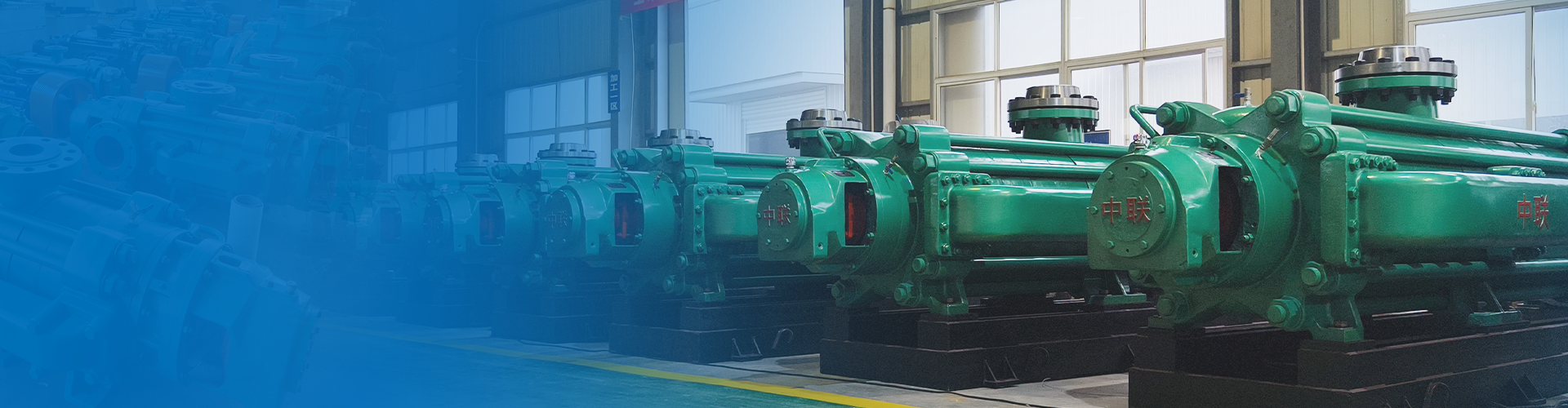
Having 26 series -312 varieties - over 1000 pump models
Focused on water pump research and development manufacturing for 36 years
Free training for operation and maintenance personnel/free installation guidance/free provision of installation drawings
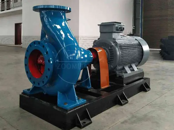


IS-type horizontal single-stage single-suction centrifugal pump
Flow rate: 3.75–1080 m³/h
Head: 4–128 m
Power: 0.55–160 kW
Efficiency: 23%-85%
Pump weight: 40–2100 kg
Cavitation margin: 2.0–6.0 m
Price: 0.19–21,500
The IS horizontal single-stage single-suction clear water pump is a pump specifically designed for clean water applications. It is suitable for industrial and municipal water supply and drainage, as well as for agricultural irrigation and drainage. It can also be used to convey clean water or other liquids with physical and chemical properties similar to those of clean water, provided the temperature does not exceed 80℃.
Hotline:
Single-stage pump
Horizontal Single-Stage Fire Pump
Product Overview
IS type Single-stage pump The IS horizontal single-stage, single-suction centrifugal pump is an energy-efficient pump jointly designed nationwide. It represents an upgraded version of the BA, BL, and other single-stage clear-water centrifugal pumps. Its advantages include: a reasonably designed hydraulic performance layout across the entire series, a wide range of options for users, and convenient maintenance; its efficiency and suction lift both reach internationally advanced average levels. The IS horizontal single-stage, single-suction pump is specifically designed for clean water applications and is suitable for industrial and municipal water supply and drainage systems. It can also be used in agricultural irrigation and drainage, as well as for conveying clean water or other liquids with physical and chemical properties similar to those of clean water, with a maximum operating temperature not exceeding 80℃.

Performance Range of IS Horizontal Single-Stage Single-Suction Clear Water Centrifugal Pumps
The IS-type single-stage pump features a simple structure, reliable performance, compact size, light weight, excellent cavitation resistance, low power consumption, and convenient operation and maintenance.
The IS-type single-stage pump boasts wide versatility and comes in a total of 140 specifications across the entire series, yet it uses only four different types of shafts. Within the same specification, the shaft, bearings, and shaft seals are all interchangeable. Moreover, the entire series of pumps features just four different types of suspensions.
Single-stage pump The rotational speeds are available in two options: 2900 and 1450 rpm.
Performance as follows: 2900 rpm, 1450 rpm
Maximum flow rate: 240 m³/min, 400 m³/min
Maximum total head: 125 meters, 55 meters
Maximum rotational speed: 3,500 rpm (when used with a 60 Hz power supply, the impeller diameter is reduced).
Maximum operating temperature: 80℃
The suction line pressure is allowed up to 0.3 MPa, while the pump's maximum operating pressure is 1.6 MPa.
Meaning of the Model Designation for IS Horizontal Single-Stage Single-Suction Clear Water Centrifugal Pumps

Structural Features of the IS Horizontal Single-Stage Single-Suction Clear Water Centrifugal Pump

1 Pump body, 2 Pump cover, 3 Impeller, 4 Shaft, 5 Seal ring, 6 Impeller nut, 7 Locking washer, 8 Shaft sleeve, 9 Stuffing box gland, 10 Stuffing ring, 11 Packing, 12 Suspension bearing assembly.
The IS horizontal single-stage single-suction clear water centrifugal pump is designed according to the performance and dimensions specified in the national standard ISO 2858. It mainly consists of the pump body (1), pump cover (2), impeller (3), shaft (4), sealing ring (5), shaft sleeve, and suspension bearing assembly (12), among other components.
The IS horizontal single-stage single-suction clear water centrifugal pump features a rear-opening design, allowing the pump cover and impeller to be disassembled without needing to remove the suction and discharge pipelines. The suspension is equipped with two ball bearings, which are lubricated using machine oil or grease. The pump is directly driven by an electric motor via an elastic coupling. The volute, base, inlet flange, and outlet flange are all cast as a single integral unit.
The pump body and cover of the IS-type centrifugal pump are split at the back side of the impeller—this is commonly referred to as the "rear-opening" structural design. Its advantage lies in its convenient maintenance: during inspection and repair, there is no need to move the pump body, suction piping, discharge piping, or motor. Instead, one only needs to remove the intermediate coupling component of the extended coupling to extract the rotor assembly for inspection and maintenance.
The pump casing—comprising the pump body and pump cover—forms the pump’s working chamber. The rotor, which includes the impeller, shaft, and rolling bearings, is housed within this chamber. The suspension bearing assembly supports the rotor components, while the rolling bearings bear both the radial and axial forces exerted on the pump.
To balance the axial force of the pump, most pumps are equipped with sealing rings both at the front and back of the impeller, and a balance hole is provided on the rear cover plate of the impeller. However, since some pumps have relatively small axial forces, their impellers do not have sealing rings or balance holes on the back side.
The pump’s axial sealing ring consists of a packing gland (9), a packing ring (10), and packing material (11) to prevent air intake or excessive water leakage. If the pump impeller is balanced, the cavity equipped with soft packing is connected to the impeller’s suction inlet. When the liquid at the impeller inlet is under vacuum, air can easily enter along the surface of the shaft sleeve. Therefore, a packing ring is installed in the packing chamber, and pressure water from the pump chamber is directed through a small hole in the pump cover to the packing ring, providing effective sealing. If the pump impeller does not have balancing holes, since the liquid pressure on the back side of the impeller exceeds atmospheric pressure, there will be no air leakage issue, and thus a packing ring is not required.
To prevent shaft wear, a shaft sleeve is installed at the point where the shaft passes through the stuffing box. An O-ring seal is fitted between the shaft sleeve and the shaft to prevent air or water leakage along the mating surfaces.
The pump is driven via an extended flexible coupling connected to the electric motor. When viewed from the drive end, the pump rotates clockwise.
Installation of IS Horizontal Single-Stage Single-Suction Clear Water Centrifugal Pump
I. Assembly and Disassembly
Before assembly, the pump’s components should first be inspected for any defects that might affect assembly, and then thoroughly cleaned before proceeding with assembly.
1. Beforehand, you can tighten the connecting bolts, threaded plugs, and other components onto their respective parts.
2. The O-ring, paper gasket, felt, and other components can be placed in advance on their respective parts.
3. The sealing ring, packing, packing rings, and packing gland can be sequentially installed into the pump cover in advance.
4. Install the rolling bearing onto the shaft, then insert it into the suspension assembly. Next, close the press cover to securely clamp the rolling bearing, and finally, slide the connecting bolts onto the shaft.
5. First, slide the shaft assembly onto the shaft; then, attach the pump cover to the suspension. Next, install and tighten the impeller, stop washer, impeller nut, and other components. Finally, assemble the above components into the pump body and tighten the connecting bolts on both the pump body and the pump cover.
During the assembly process described above, certain small components—such as flat keys, oil seals, water-sealing bushings, and O-rings for shaft sleeves—can easily be overlooked or installed in the wrong sequence. Special attention should be paid to these parts.
The pump disassembly sequence can basically be carried out in the reverse order of the assembly sequence.
II. Installation
The quality of pump installation significantly affects the pump’s operation and service life; therefore, installation and alignment must be carried out with great care. Refer to the pump’s external dimensions and installation dimensions.
1. Installation and Calibration:
1) Remove grease and dirt from the base, then place the base onto the foundation.
2) Use a level to check the horizontality of the base; wedge irons may be used for leveling if necessary.
3) Pour cement into the base and anchor bolt holes.
4) After the cement has fully dried, check whether the base and anchor bolt holes are loose. Once they are found to be secure, tighten the anchor bolts and recheck the levelness.
5) Clean the supporting surface of the base, as well as the surfaces where the pump feet and motor feet will be mounted. Then, install the water tank and the motor onto the base.
6) A certain gap should be maintained between the couplings. Check whether the centerlines of the pump shaft and the motor shaft are aligned; thin shims can be used to adjust them for concentricity.
7) The difference between the upper and lower, as well as the left and right, edges of the coupling shall not exceed 0.1 mm. The maximum and minimum gaps around the circumference of the end faces of the two couplings shall not differ by more than 0.3 mm.
2. Installation Instructions:
1) The installation height of the centrifugal pump, as well as the length, diameter, and flow rate of the pipeline, should conform to the calculations and strive to minimize unnecessary losses.
2) When transporting over long distances, a larger pipe diameter should be used. The pump’s pipeline should have its own supports, and the weight of the pipeline must not be allowed to bear on the pump, to avoid damaging the pump.
3) If a check valve is installed on the discharge pipeline, it should be positioned outside the gate valve.
III. Starting, Stopping, and Operation
1. Start:
1) Before connecting the machine, ensure that the motor’s rotation direction is correct and that the pump operates smoothly.
2) Close the idle valves on the discharge pipeline.
3) Fill the pump with water, or use a vacuum pump to prime it.
4) Once the power is turned on and the pump reaches its normal speed, gradually open the gate valve on the discharge pipeline and adjust it to the desired operating conditions. Under the condition that the gate valve on the discharge pipeline remains closed, the pump must not run continuously for more than 3 minutes.
2. Stop:
1) Gradually close the gate valve on the discharge pipeline and disconnect the power supply.
2) If the ambient temperature falls below 0℃, the water inside the pump should be drained to prevent freezing and cracking.
3) If the pump is to be discontinued for an extended period, it should be disassembled, cleaned, lubricated, and then properly packaged and stored.
3. Operation:
1) During driving and operation, you must pay close attention to whether the instrument readings, bearing temperature rise, packing leakage and heating, as well as vibrations and abnormal noises, are normal. If any abnormalities are detected, they should be addressed immediately.
2) The maximum bearing temperature shall not exceed 80℃, and the bearing temperature shall not exceed the ambient temperature by more than 40℃.
3) The packing is normal; any leakage should be slight and uniform.
4) The bearing oil level should be maintained at the normal position—neither too high nor too low. If the oil level is too low, lubricating oil should be replenished promptly.
5) If the clearance between the sealing ring and the impeller mating surfaces is excessively worn, the sealing ring should be replaced with a new one.
Product Parameters
IS Type Horizontal Single-Stage Single-Suction Clear Water Centrifugal Pump Model Parameter Table
| Model | Traffic | Head height | Efficiency | Motor power |
| (m³/h) | (m) | (%) | (kW) | |
| IS50-32-125(2900) | 12.5 | 20 | 60.3 | 2.2 |
| IS50-32-125A(2900) | 11.2 | 16 | 58 | 1.5 |
| IS50-32-160(2900) | 12.5 | 32 | 54 | 3 |
| IS50-32-160A(2900) | 11.7 | 28 | 53 | 2.2 |
| IS50-32-160B(2900) | 10.8 | 24 | 50 | 1.5 |
| IS50-32-200(2900) | 12.5 | 50 | 48.1 | 5.5 |
| IS50-32-200A(2900) | 11.7 | 44 | 45 | 4 |
| IS50-32-200B(2900) | 10.8 | 38 | 43 | 4 |
| IS50-32-250(2900) | 12.5 | 80 | 38.1 | 11 |
| IS50-32-250A(2900) | 11.7 | 70 | 35 | 7.5 |
| IS50-32-250B(2900) | 10.8 | 60 | 36 | 5.5 |
| IS50-32-125(1450) | 6.3 | 5 | 54 | 75 |
| IS50-32-125A(1450) | 5.6 | 4 | 53 | 0.55 |
| IS50-32-160(1450) | 6.3 | 8 | 48 | 0.55 |
| IS50-32-160A(1450) | 5.8 | 4.6 | 46 | 0.55 |
| IS50-32-160B(1450) | 5.4 | 4.1 | 43 | 0.55 |
| IS50-32-200(1450) | 6.3 | 12.5 | 42.1 | 0.55 |
| IS50-32-200A(1450) | 5.8 | 11 | 40 | 0.75 |
| IS50-32-200B(1450) | 5.4 | 9.5 | 38 | 0.55 |
| IS50-32-250(1450) | 6.3 | 20 | 32.1 | 0.55 |
| IS50-32-250A(1450) | 5.8 | 17.5 | 30 | 1.5 |
| IS50-32-250B(1450) | 5.4 | 15 | 26 | 1.1 |
| IS65-40-200(2900) | 25 | 50 | 60.1 | 3 |
| IS65-40-200A(2900) | 23.4 | 44 | 57 | 2.2 |
| IS65-40-200B(2900) | 21.8 | 38 | 55 | 5.5 |
| IS65-40-250(2900) | 25 | 80 | 50 | 4 |
| IS65-40-250A(2900) | 23.4 | 70 | 49 | 3 |
| IS65-40-250B(2900) | 21.7 | 60 | 47 | 7.5 |
| IS65-40-315(2900) | 25 | 125 | 50 | 5.5 |
| IS65-40-315A(2900) | 23.9 | 114 | 38 | 5.5 |
| IS65-40-315B(2900) | 22.7 | 103 | 37 | 15 |
| IS65-40-315C(2900) | 21.4 | 92 | 35 | 11 |
| IS65-40-200(1450) | 12.5 | 12.5 | 55.3 | 1.1 |
| IS65-40-200A(1450) | 11.7 | 11 | 51 | 0.55 |
| IS65-40-200B(1450) | 10.8 | 9.5 | 48 | 0.55 |
| IS65-40-250(1450) | 12.5 | 20 | 46 | 0.75 |
| IS65-40-250A(1450) | 11.7 | 17.5 | 46 | 0.55 |
| IS65-40-250B(1450) | 10.8 | 15 | 44 | 0.55 |
| IS65-40-315(1450) | 12.5 | 32 | 37.1 | 1.1 |
| IS65-40-315A(1450) | 11.9 | 28.5 | 35 | 1.1 |
| IS65-40-315B(1450) | 11.3 | 25.8 | 34 | 0.75 |
| IS65-40-315C(1450) | 10.7 | 23 | 32 | 2.2 |
| IS65-50-125(2900) | 25 | 20 | 69.2 | 11 |
| IS65-50-125A(2900) | 22.4 | 16 | 66 | 30 |
| IS65-50-160(2900) | 25 | 32 | 65.1 | 22 |
| IS65-50-160A(2900) | 23.4 | 28 | 63 | 18.5 |
| IS65-50-160B(2900) | 21.7 | 24 | 60 | 15 |
| IS80-50-200(2900) | 50 | 50 | 69 | 5.5 |
| IS80-50-200A(2900) | 46.8 | 44 | 67 | 4 |
| IS80-50-200B(2900) | 43.6 | 38 | 66 | 7.5 |
| IS80-50-250(2900) | 50 | 80 | 63 | 5.5 |
| IS80-50-250A(2900) | 46.8 | 70 | 60 | 5.5 |
| IS80-50-250B(2900) | 43.3 | 60 | 58 | 15 |
| IS80-50-315(2900) | 50 | 125 | 54.1 | 11 |
| IS80-50-315A(2900) | 47.8 | 108 | 51 | 7.5 |
| IS80-50-315B(2900) | 45.4 | 103 | 49 | 22 |
| IS80-50-315C(2900) | 42.9 | 92 | 47 | 18.5 |
| IS80-50-200(1450) | 25 | 12.5 | 65 | 3 |
| IS80-50-200A(1450) | 23.4 | 11 | 64 | 0.75 |
| IS80-50-200B(1450) | 21.8 | 9.5 | 63 | 0.75 |
| IS80-50-250(1450) | 25 | 20 | 60 | 1.5 |
| IS80-50-250A(1450) | 23.4 | 17.5 | 57 | 1.1 |
| IS80-50-250B(1450) | 21.7 | 15 | 55 | 0.75 |
| IS80-50-315(1450) | 25 | 32 | 52 | 2.2 |
| IS80-50-315A(1450) | 23.9 | 28.5 | 49 | 1.5 |
| IS80-50-315B(1450) | 22.7 | 25.8 | 46 | 1.1 |
| IS80-50-315C(1450) | 21.4 | 23 | 44 | 3 |
| IS80-65-125(2900) | 50 | 20 | 75.1 | 15 |
| IS80-65-125A(2900) | 44.7 | 16 | 73 | 37 |
| IS80-65-160(2900) | 50 | 32 | 73 | 37 |
| IS80-65-160A(2900) | 46.8 | 28 | 70 | 30 |
| IS80-65-160B(2900) | 43.3 | 24 | 68 | 30 |
| IS80-65-125(1450) | 25 | 5 | 71 | 3 |
| IS80-65-125A(1450) | 22.4 | 4 | 69 | 2.2 |
| IS80-65-160(1450) | 25 | 8 | 69 | 5.5 |
| IS80-65-160A(1450) | 23.4 | 7 | 66 | 5.5 |
| IS80-65-160B(1450) | 21.7 | 6 | 64 | 4 |
| IS100-65-200(2900) | 100 | 50 | 76.1 | 11 |
| IS100-65-200A(2900) | 93.8 | 44 | 75 | 7.5 |
| IS100-65-200B(2900) | 87.2 | 38 | 72 | 15 |
| IS100-65-250(2900) | 100 | 80 | 71.9 | 11 |
| IS100-65-250A(2900) | 93.5 | 70 | 70 | 11 |
| IS100-65-250B(2900) | 86.6 | 60 | 68 | 22 |
| IS100-65-315(2900) | 100 | 125 | 66 | 18.5 |
| IS100-65-315A(2900) | 95.5 | 109 | 64 | 15 |
| IS100-65-315B(2900) | 90.8 | 95 | 62 | 37 |
| IS100-65-315C(2900) | 85.8 | 92 | 60 | 30 |
| IS100-65-200(1450) | 50 | 12.5 | 73.1 | 4 |
| IS100-65-200A(1450) | 46.9 | 11 | 72 | 1.5 |
| IS100-65-200B(1450) | 43.6 | 9.5 | 69 | 1.1 |
| IS100-65-250(1450) | 50 | 20 | 68.1 | 2.2 |
| IS100-65-250A(1450) | 46.8 | 17.5 | 66 | 1.5 |
| IS100-65-250B(1450) | 43.3 | 15 | 64 | 1.5 |
| IS100-65-315(1450) | 50 | 32 | 63 | 4 |
| IS100-65-315A(1450) | 47.7 | 28.5 | 61 | 3 |
| IS100-65-315B(1450) | 42.9 | 23 | 57 | 2.2 |
| IS100-80-125(2900) | 100 | 20 | 77.9 | 30 |
| IS100-80-125A(2900) | 89.4 | 16 | 70 | 75 |
| IS100-80-160(2900) | 100 | 32 | 77.9 | 55 |
| IS100-80-160A(2900) | 93.5 | 28 | 75 | 45 |
| IS100-80-160B(2900) | 86.6 | 24 | 73 | 37 |
| IS100-80-125(1450) | 50 | 5 | 74.9 | 5.5 |
| IS100-80-125A(1450) | 44.7 | 4 | 66 | 5.5 |
| IS100-80-160(1450) | 50 | 8 | 75.2 | 5.5 |
| IS100-80-160A(1450) | 46.8 | 7 | 72 | 11 |
| IS100-80-160B(1450) | 43.3 | 6 | 70 | 7.5 |
| IS125-80-160(2900) | 160 | 32 | 79.7 | 22 |
| IS125-80-200(2900) | 160 | 50 | 80.1 | 15 |
| IS125-80-250(2900) | 160 | 80 | 77 | 37 |
| IS125-80-315(2900) | 160 | 125 | 73.1 | 55 |
| IS125-80-160(1450) | 80 | 8 | 77.2 | 5.5 |
| IS125-80-200(1450) | 80 | 12.5 | 77 | 4 |
| IS125-80-250(1450) | 80 | 20 | 74 | 5.5 |
| IS125-80-315(1450) | 80 | 32 | 70 | 11 |
| IS125-80-400(1450) | 87.6 | 60 | 63.1 | 15 |
| IS125-100-200(2900) | 200 | 50 | 81.1 | 90 |
| IS125-100-200A(2900) | 187 | 44 | 78 | 45 |
| IS125-100-200B(2900) | 173 | 38 | 77 | 37 |
| IS125-100-250(2900) | 200 | 80 | 78 | 30 |
| IS125-100-250A(2900) | 187 | 70 | 76 | 75 |
| IS125-100-250B(2900) | 173.2 | 60 | 74 | 55 |
| IS125-100-315(2900) | 200 | 125 | 75 | 45 |
| IS125-100-315A(2900) | 191 | 114 | 73 | 110 |
| IS125-100-315B(2900) | 181.5 | 103 | 71 | 90 |
| IS125-100-315C(2900) | 171.6 | 92 | 69 | 75 |
| IS125-100-200(1450) | 100 | 12.5 | 76 | 7.5 |
| IS125-100-200A(1450) | 93.5 | 11 | 73 | 5.5 |
| IS125-100-200B(1450) | 87.2 | 9.5 | 71 | 4 |
| IS125-100-250(1450) |